In Hungary, the KNX system started to spread in the mid-90s and thanks to the excellent Hungarian experts, countless buildings have been built with KNX technology since then. They are still working reliably today! But what makes this standard so stable and versatile?
Setup and operation
In a conventional electrical installation, the consumers are always connected to the main circuit. The switch and/or sensor is connected directly or via a relay to the consumer. The design of the wiring between the switch or sensor and the consumer determines the operation of the connected consumer. In KNX technology, the consumer is connected indirectly when installed. All the actuators, called sensors, and the actual switching elements, called actuators, are connected via a common transmission medium. Thus, when a control button is pressed, it sends information (a telegram) through the transmission medium to the executive unit (actuator), which then executes the command, switching the load. A KNX standard allows the use of multiple physical transmission channels. You can work with twisted pair (TP), use power line (PL), build radio frequency (RF) or IP-based networks. In practice, we mostly use twisted pair technology. This is because it is the most stable transmission medium. The stability of transmission can be affected by many factors. For example, RF transmission becomes unstable when used in a building larger than optimal, but it is also adversely affected by the shielding effect of reinforced concrete structures. Cabling is not affected by these factors. However, many disturbing factors remain, such as high electromagnetic radiation in industrial environments or extreme temperature conditions. Fortunately, the KNX Association sets very strict technical requirements for KNX manufacturers and only devices that comply with the standard in all respects can be KNX certified.
The line is the basic unit
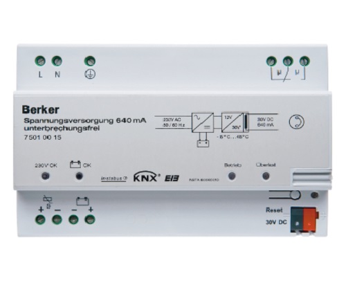
Since TP transmission is the most common in practice, we will start with this solution in the technical description. When using bus cable transmission, the KNX system is hierarchical, consisting of lines and domains (areas). The smallest installation unit is the line, to which the individual devices are connected. A line can consist of a maximum of 4 segments, each containing a maximum of 64 participants. The actual number of participants on a line may depend on the power supply selected and the power requirements of each device. Each line must be supplied with a power supply. This will ensure the power supply of the KNX devices. The power supply supplies the power to the communication part of all the devices, and this is how the devices communicate with each other. In practice, it is a pair of wires. It carries the power and the signal is connected to it.
The range
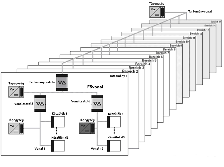
Since you can have up to 64 devices on a line, you only need to start another line if you need more. By default, the line is not extended with new segments, but rather several lines are used side by side. However, in detached houses, separate lines are sometimes added on different floors of the building, even if the number of appliances does not justify it. The lines on each floor are thus connected by a main line, and this structure is now called a range. There can be a total of 15 lines in a range. Each line is connected to the tank via a so-called line coupler (LC). This galvanically separates the line from the main line. We have to put a power supply on each line, and the same for the main line. Therefore, the more lines and main lines, the more extra power supplies the system needs.
More provinces
When 15 lines are no longer sufficient, or when for some practical reason you want to segment the system better, you may need to create several domains in parallel. In this case, they are connected by a range coupler which, like the line coupler, galvanically separates the two sides. This line is called the range line. Devices can be placed on both the main lines and the range line, although the latter is in practice more commonly used only for the transmission of communications. Of course, the range line must also be equipped with a power supply. Since fifteen ranges can be connected together, there can be a total of 15x15x64x4 devices on a KNX system. This means a total of 57 600 devices. This is a very large number, as each device can have up to 20 independent outputs. However, if even this is not enough, the system can be further extended via IP interfaces. In practice, IP interconnection is more commonly used only to connect buildings that are far apart - for example, a multinational company's buildings that are far apart, even on different continents.
Domain Attachment
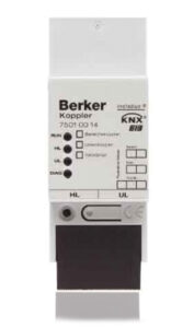
The range coupler, line coupler and line amplifier are in practice the same device. Its position in the topology and its function determines whether it is a range, line coupler or line amplifier. The function that determines its operation can be specified at the time of programming. There are several advantages to dividing the system into lines and ranges. Firstly, it increases the reliability of operation, since the lines and ranges are supplied by their own power supply and are therefore electrically isolated. Thus, if a failure occurs within a line, the rest of the system continues to operate without disruption. On the other hand, the local data traffic on one line or domain does not affect the data throughput of the other lines and domains. This speeds up communication. Thirdly, the division into lines and domains keeps the KNX system transparent, which is important during commissioning and facilitates diagnostic testing and maintenance.
The topology discussed above has in effect described the hierarchical structure of the system. For the cabling of individual lines, the standard allows for star point, bus, tree and sometimes even ring topologies. In practice, the latter is avoided because it can cause surge problems, for example in the event of a lightning strike. The most common topology is a combination of the first three. In practice, the bus line will be routed to the easiest route. After all, the system is connected in any way. The only important thing is that all devices receive the bus line. Of course, the line on which it is designed to be.