Bus cable as a transmission device
Recessed mounting
If flush-mounted devices are used, fitting boxes suitable for screw fixing in accordance with DIN VDE 0606-1 or DIN 49073-1 must be used. If more than two bus cables run into one fitting box, it is advisable to use a 60 - mm deep combined wall junction box. The combination of a bus device and a socket under a common cover plate is only permitted if the socket is designed in such a way that it is protected against direct contact and if the design complies with DIN VDE.
Cable entry
The cable entry of the KNX system can be implemented within the installation zone according to DIN 18015-3, together with the power entry. Ceiling or downward, floor-guided cable entry is possible, depending on the network design. The bus wiring of each room can be routed individually to the electrical distribution board (star topology) or looped from room to room. The division into lines and ranges must be taken into account. The distributors within the building (the main distributor and the sub-distributors) should always be connected to each other by bus cable.
Levels or larger areas should in principle be connected to the (main) hub by a direct (point-to-point) connection. There should be a place within the building where each system, e.g. 230/400 V mains, KNX, TV and telephone networks are available in one place (at the main distributor, at the connection point) so that the connection between the systems can be made via media interface.
Installation method
Bus cable as a means of transmission
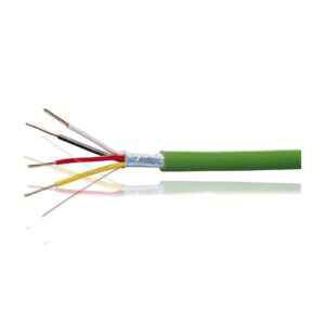
In the KNX system, shielded double twisted pair cables with 0.8 mm diameter solid core are used as bus cables, e.g. YCYM 2 x 2 x 0.8. Power transmission cables used in security, telephone and other electrical networks cannot be used as bus cables.
The bus cable, just like the transmission cables, can be laid in defined installation zones in line, tree or star structure according to DIN 18015:
- Can be laid together with other circuit cables in conduit and duct;
- If a halogen-free cable is required, type J-H(St)H 2 x 2 x 08 can be used.
- Lines should not be looped if there is branching during installation, i.e. different lines should not be joined.
- To connect two buildings, use the underground A2Y(L)2Y or A-2YF(L)2Y telecommunication cable.
- Surge protection is covered in Chapter 6.
You can also use the unused pair of wires in the bus cable for other applications, in which case you should consider the following:
- Only the SELV/PELV dummy voltage can be used for the KNX system;
- A maximum current of 2.5A is permanently allowed, overload and short circuit protection is required in the power supply;
- Voice transmission is allowed, but you cannot use the wire as a public telecommunications network transmission cable;
- There can be only one use of the second pair of coins within a line;
- In addition, it is advisable to clearly mark the twisted pairs of wires at each end of the wires if they are to be used for some additional purpose;
- If the second pair of wires is to be used as an additional line, the yellow wire should be assigned to the "+" wire and the white wire to the "-" wire.
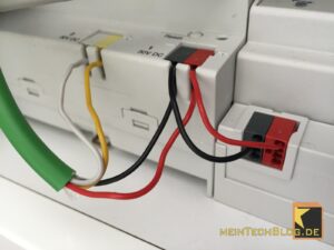
An assembly box may contain bus and power conductor wires, but only if the bus and power conductor wires are securely separated in the box. If the fitting box has fixed terminals, boxes without permanent separation may be used. Otherwise, separate fitting boxes for the bus cable and power wires shall be used.
In a KNX bus system, the power cable and the bus cable, as well as the necessary fittings, can be placed next to each other in a distribution box.
The following should be taken into account:
- Double plastic insulated power transmission cables and double insulated bus cables can be laid side by side without separation, and insulated power transmission cables can also be laid side by side;
- The insulated core of single plastic-insulated power transmission cables and bus cables can only be laid at a certain distance from each other;
- Insulated cores of transmission cables and bus cables shall be laid at least 4 mm apart or shall be provided with equivalent insulation, which may be a separating plate or insulating tube on the bus cable core.
This solution shall be used for cable cores belonging to other circuits which do not comply with the SELV/PELV dc voltage circuit requirements.
If, in the case of flush mounting, bus devices and transmission devices are used together, the power section shall be protected against direct contact even if the common enclosure is removed (e.g. by a separate cover).
In the case of flush-mounted installations, where there is both a bus device and a transmission device, "safety isolation" must be provided at the design stage. Manufacturers' data should be taken into account. Particular attention must be paid to these aspects in harsh, severe environmental conditions (overvoltage rating, polluted environments). Compared to a public telephone network, the bus system and its components should be considered as a high-current electrical network. This applies to any communication network that is not a SELV/PELV extra-low voltage circuit.
In the case of SELV/PELV extra-low voltage circuits, the basic insulation should be reinforced according to the voltage stress, so that it is not necessarily necessary to lay such cables separately from the bus cable. Bus devices, such as those used in the construction of a bus system, which are not designed for the use in the field of power supply, are not required to be installed in the bus. They can be installed in the electrical sub-distribution board, DIN-rail mounted or recessed, possibly mounted outside the wall or even inside the equipment (e.g. in a light fitting). It is also possible to install any bus device in a trunking.
A separate circuit is recommended for connecting the power supply to the mains. The power supply should be placed in the middle of the line. Only power supplies approved by the KNX organisation should be used in the system.
If the electrical power supply needs to be provided with reinforced safety, the KNX power supply can be connected to an uninterruptible power supply, a safety power supply or a battery-operated power supply can be used in the KNX system.