As one of the world's leading building automation solutions for residential and public buildings, KNX system naturally also offers sophisticated solutions for shading control. As there are many different types of shading devices on the market and the way they are controlled varies widely, it is not possible to solve everything with one device. The best way to go is always to use devices developed for the specific task (equipment).
The easiest to control are shutter motors that operate at 230 V and have separate up and down directions. These are the most common motors available on the market. In such cases, it is necessary to use shutter control outputs that can switch 230 V and have a mechanical interlock between the up and down directions. This is necessary to ensure that it is not possible, even accidentally, to output voltage in both directions simultaneously. After all, one of the basic requirements for controls is to protect the integrity of the equipment to be controlled (in this case the shutter motor).
It is also important to note that you should never connect roller shutter motors in parallel! So, either connect the drive of each motor to a separate output, or control the motors in parallel with each other by disconnecting them with relays.
Blinds control actuator

In a KNX shutter control actuator, you can usually set the run-up and run-down times, as well as the lamella switching time. If these are set precisely (individually for each shutter), it is possible to position the shutter motors for simple shutter motors, which otherwise only have up and down directional outlet. This means that if you want to move your shutter to a preset position with a single button press or some kind of trigger, you can do it with a 1 byte value assignment. Of course, this is also true for the slat position (if we have slat blinds). Of course, this requires measuring the running times for each blind individually, so that we can set the desired positions accurately. Up and down times should be measured separately, as the down time for a roller shutter is usually a little less than the up time, because gravity makes the down time shorter. Of course, there may be other cases. Since positioning here depends on accurate measurement of the running times - which admittedly is not entirely exact - it may be useful to set up your actuators so that at certain intervals the shutters automatically take a reference point shot from which the timing is reset. In this case, even if there is minimal slippage in the system, they will not add up - thanks to the regular reference recording.
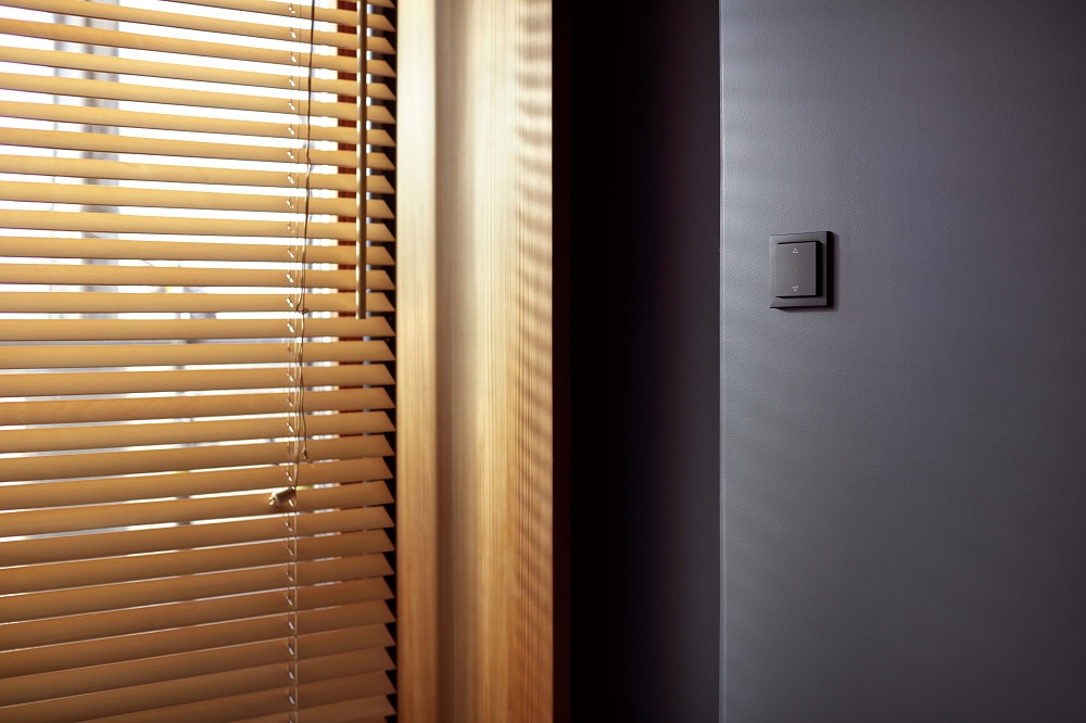
Limit switch
Although the shutter motors have limit switches, the shutter control actuators can be set to switch off the outputs after a certain time, so that the wires to the motor are not de-energised. In such a case, a new parameter is set to set the runtime values and a slightly longer time for the output to switch off after this time. In this time, it should be safe for the shield to reach from one end position to the other. In almost all these shutter controls, the change of direction time can be set. This is necessary because, in order to increase the life of our shutter motor, we do not apply the voltage in both directions for even a short time at a time, but the user can suddenly start the up direction while the shutter is running in the down direction. A large roller shutter, due to its inertia, will still move downwards for some time (even if we are talking about tenths of a second) if it no longer receives downward voltage. In such cases, it is not advisable to apply the reverse voltage to the motor immediately. Therefore this time can be set as a separate parameter.
There are shading solutions on the market that can be controlled not by 230 V but by, say, 24 V DC. In these cases, the relay output in the 230 V shutter actuators could obviously also switch 24 V DC, but a different solution is still needed. Because in most cases, the change of direction for 24 V DC motors can be solved by reversing the polarity, and this requires actuators that do not simply have normally closed outputs, but solve the polarity reversal themselves.
To complicate matters further, some motors, such as curtain movers in many cases, can be started by a pulse in one direction or the other and stopped by another pulse in the same or the opposite direction. In such cases, it is necessary to choose KNX actuators and controls that are capable of controlling the shutter by pulses.
Use of motors
In cases where SMI motors are used, they can be strung onto an SMI bus, so that SMI control and power is supplied to the motors. The intervention itself (processing of the control signals) is done in the motor, as in this case there is also direct communication between the KNX system and the motor, allowing a much more precise control, but with a more limited choice of available motors.
If you use KNX-compatible motors from the start, the possibilities are almost endless. In such cases, there is a direct link between the motor and the system. It is possible to know exactly what position the motor is in, e.g. whether there is a blockage or other non-operational state.
The construction of the power trail depends on the type of motor (control) and how much selective protection you want to provide, as well as the preparation for any subsequent electrical modifications. If this is possible, the most practical solution is to wire each electric shutter (motor) to be controlled into the distribution box. In this case, all electrical modifications can be easily made in the distribution boxes without having to touch anything in the field, and selective overcurrent protection can also be easily achieved. Occasionally, due to an installation fault, a shutter may become shorted, for example, the motor may wind up the incoming power cable. In such a case, if the individual motors are wired separately into the distribution board, they can be easily disconnected while the shutter installer is working on the fault and it will not cause any disruption to the other circuits.